Array Probe Pitch: It Sets Steering Range, Not Resolution
Same symptom on your system?
Tell us your model and what it is doing. A GEPROBE engineer replies with a diagnosis path, part options and pricing — usually within 6 hours, with no obligation.
Chat on WhatsApp
A phased array you can measure from its own published numbers
An intracardiac echocardiography catheter described in the IEEE Ultrasonics Symposium literature carries three numbers that can be checked against each other: 64 elements, a 7.0 MHz nominal imaging frequency, and a 7.0 mm azimuth aperture. Divide the aperture by the element count and a fourth number falls out — about 110 µm — and the source states it directly: the array is built at 110 µm pitch.
That is the pitch. It is the distance from the centre of one element to the centre of the next, and it is the sum of two other things: the width of the piezoelectric element and the kerf, the saw cut that separates it from its neighbour. Pitch is not the kerf, and it is not the element width. Documentation quotes all three inconsistently — sometimes pitch, sometimes element size plus kerf, sometimes an aperture and an element count you have to divide — and the two numbers people reach for first are usually the wrong two. A narrow kerf does not mean a dense array, and a wide element does not mean a wide pitch.
Two relationships make that catheter's numbers readable. At 7 MHz in tissue at 1540 m/s a wavelength is 220 µm, so 110 µm is exactly half a wavelength. And 64 elements across 7 mm is a small aperture — not because the designer wanted a small one, but because the array has to fit inside a catheter that crosses the atrial septum. The aperture was given; the pitch was designed. That is the whole logic of array geometry working in both directions at once: a steered array is built at half a wavelength, and the aperture is whatever the anatomy has left over.
The rest of this page is about which of those two numbers anyone is allowed to move — and, once the probe is built, the answer is usually neither.
Resolution has three axes, and pitch is not on any of them
Lateral resolution, the ability to separate two reflectors side by side, is set by the width of the beam at the depth of interest. The beam width is set by the wavelength and the F-number, which is focal depth divided by active aperture; the usual estimate for a focused aperture, δ ≈ 1.02 Z0 λ / d, contains aperture and wavelength and nothing else. Two consequences follow that are worth keeping apart. The first is that lateral resolution is depth-dependent: it is best at the focus and degrades on either side of it, along a curve that no element spacing adjusts. The second is that the cheapest way to buy lateral resolution is a larger active aperture — and the active aperture is not the same thing as the array. It is the part of the array the beamformer is using at that depth.
Axial resolution runs on a different mechanism with a different variable. It comes from the length of the pulse in space, and the practical limit is half the spatial pulse length. Frequency and damping set that length. Element spacing has no term in it.
Elevation, the third axis and the one that shows up as slice thickness, is set by the element height and the acoustic lens in front of it.
Above all three sits the directivity of a single element, which is a property of element width. A wider element radiates into a narrower cone, and that narrows the range of F-numbers the array can reach: the achievable F-number rises, and a higher F-number means a wider main lobe and therefore worse resolution. This is the mechanism behind a counter-intuitive result in the recent large-element literature, where doubling element size doubled the field of view at no extra element count and paid for it in resolution that had to be recovered by a more capable beamformer.
Element width and pitch do meet in one specific place. The nulls of the element directivity sit at mλ/W and the grating lobes of the array factor sit at mλ/d, so the two families only coincide when the element width equals the pitch — which means a kerf of zero, and therefore no array at all. Any real kerf pushes the nulls outward relative to the lobes and lets some grating-lobe energy back into the beam pattern.
| Quantity | What actually sets it | Where pitch enters |
|---|---|---|
| Axial resolution | Pulse length: centre frequency and damping, with a floor of about half the spatial pulse length | Not present |
| Lateral resolution | Wavelength, active aperture and focal depth, that is, the F-number | Only through the aperture a channel budget can afford |
| Slice thickness | Element height and the acoustic lens | Not present |
| Side-lobe level | Aperture weighting, and the directivity of the individual element | Not present |
| Grating-lobe onset | Pitch relative to the shortest wavelength in the pulse, and the steering angle | This is the one |
| Element count for a fixed aperture | Pitch | This is the other one |
| Sensitivity and signal-to-noise | Active area, and how many channels contribute | Indirectly, because element width is pitch minus kerf |
Two rows out of seven. That asymmetry is what a conversation about a small-pitch probe is actually about, because it says what such a probe is for: not a sharper image, but a beam that can be steered further before a second, equally strong version of it appears somewhere it was not aimed.
Grating lobes are what a pitch that is too large produces
A periodic array is a sampled aperture. Its beam pattern is the array factor, the Fourier transform of a set of equally spaced points, and the transform of a sampled function repeats. The repetitions are the grating lobes. For an unsteered array the first one appears at sin θ = λ/d. Steering moves the whole family with it: at a steering angle θ the array factor places a lobe at sin θ ± mλ/d, so as the beam swings towards the edge of the sector, the first grating lobe swings towards the middle of it.
Three conditions come out of that, and they are not equally strict. A pitch below one wavelength keeps the first grating lobe outside the visible region for an unsteered beam, which is why a linear probe that only ever scans straight ahead can live at a pitch close to λ — the traditional array families differ in exactly this respect, as our note on transducer technology sets out. A pitch of λ/2 keeps it out under any focusing and steering condition, which is what a phased sector array is built to. And if an application only needs to steer as far as some angle θ, the requirement relaxes to d ≤ λ/(1 + sin θ) — the expression worth remembering, because it states the trade in one line. The further you need to steer, the smaller the pitch has to be.
The wavelength in those expressions is not the centre wavelength. A wideband probe has to satisfy the condition at the shortest wavelength in its pulse, which is at the top of its band. The same geometry that is safe at the nominal frequency can therefore produce grating lobes when the system drives it at its upper limit, and this is one of the reasons a broadband probe and a narrowband probe with the same centre frequency are not interchangeable designs even when their apertures match.
What a grating lobe does in an image is specific rather than general. It is a second main lobe rather than a weakened one, so an echo arriving from the grating-lobe direction is indistinguishable from an echo on the intended axis and is displayed as if it belonged there: correct depth by time of flight, wrong direction. A strong reflector outside the intended field of view reappears as a duplicate somewhere else in the image, and regions that should read dark fill in. The damage is to contrast, because the artifact adds energy to the diagnostic signal instead of removing it. What limits the grating lobe is not the aperture weighting but the directivity of the individual elements, which is the one mechanism that stops it from being as strong as the main lobe it mirrors.
The arithmetic of the condition is small enough to do in the head, and it explains a design pattern. Take a 2 cm aperture at 8 MHz with 100% fractional bandwidth. The top of the band is 12 MHz, where the wavelength in tissue is about 128 µm. At a half-wavelength pitch that aperture needs roughly 312 elements; at a full-wavelength pitch, roughly 156. The university course material that runs this calculation adds the constraint that decides the argument: a commercial scanner generally addresses a maximum of about 256 elements. The choice is therefore not between a careful array and a lazy one. It is between steering range and channel count — and for a linear array that only scans straight ahead, the second is the scarce one.
Side lobes come from a different mechanism, so amplitude will not identify them
Side lobes do not need an array at all. They are the diffraction pattern of a finite aperture: any aperture of finite width radiates some energy outside its main beam. For a uniformly excited aperture the first side lobe sits a little over a decade below the main lobe on a decibel scale — reported in the beamforming literature at roughly 16 dB below the main lobe for a typical linear array, and pushed below 50 dB down by a Hamming weighting applied on receive. That improvement is not free. The same weighting widens the main lobe, which is why side-lobe suppression and lateral resolution tend to be discussed in the same breath, and why a family of adaptive beamformers exists that suppress side lobes without widening the main beam, at a substantial computational cost.
The clinical consequence is documented in detail, because the mechanism has a recognisable signature. Energy in a side lobe is mostly dissipated in tissue without any reflection at all. When it does meet a strong reflector — a wire, a calcification, a prosthetic ring, the pericardium — the returning echo enters the receiver alongside the wanted signal, and the scanner, which assumes that every echo came back along the central axis, displays it there. As the beam sweeps, a succession of such placements forms an arc at a fixed radial distance from the transducer. Reviews of cardiac ultrasound artifacts list the resulting errors among the ones that change diagnoses rather than merely degrade pictures: side-lobe artifacts from highly reflective interfaces have been mistaken for intracardiac thrombus or vegetation, and artifacts from the aortic sinotubular junction for a dissection flap.
Side lobes and grating lobes are usually discussed as one nuisance with two names, and they are not one thing. A side lobe is a property of an aperture of finite width and would survive the aperture being continuous. A grating lobe is a property of periodic sampling and disappears when the sampling is fine enough. They respond to different fixes, and that is the practical difference. A grating lobe's angular position is tied to the steering angle through the array factor, so it moves when the beam is re-steered and vanishes when the pitch is reduced. A side lobe's angular structure is tied to the aperture weighting and to the element's own directivity, so it does not move with steering and does not care about pitch at all. Which is also why peak amplitude cannot be used to tell them apart: a grating lobe produced at the top of a wide band can sit lower than a side lobe produced by a heavily tapered aperture, and the ranking of those two numbers says nothing about which mechanism put the echo in the image.
Why not build every array at half a wavelength
Four things stand in the way, and they arrive in this order:
- Channels. At a fixed aperture, halving the pitch doubles the element count. The 2 cm example above is the whole story: 312 elements against 156 for the same physical aperture, measured against a scanner that generally addresses about 256. Half a wavelength across a wide aperture is a specification that does not close.
- Fabrication. A half-wavelength pitch is about 154 µm at 5 MHz, about 26 µm at 30 MHz, and roughly 11 µm at 70 MHz. At those scales the limit is not the element but the cut between elements. A fabrication review of high-frequency arrays puts the dice-and-fill blade limit at a 10-15 µm kerf, workable below roughly 20 MHz — which is part of why high-frequency imaging spent years as a single-element rather than an arrayed technique.
- The kerf-to-pitch ratio. Because the element-factor nulls that can cancel grating lobes sit at mλ/W while the grating lobes sit at mλ/d, the cancellation needs the element width and the pitch to be equal. With a kerf that cannot be reduced any further, shrinking the pitch shrinks the element with it and moves the two families further out of alignment. A smaller pitch therefore buys a larger safe steering angle and gives back part of the element's own suppression of the grating lobe. The minimum manufacturable kerf is the optimum; the maximum is not.
- The aperture you were after. If the element count is capped by the system, the only way to keep both a half-wavelength pitch and a wide aperture is to activate a subset of the elements — a sparse array. The two costs of sparsity are consistent across three decades of the literature: the beam profile deteriorates, which is a contrast problem, and the signal-to-noise ratio falls because fewer elements contribute. A gap-filling study quantifies the first: a sparse receive aperture raises the grating-lobe level relative to a fully sampled one, and virtually filling the empty positions recovers up to 16 dB of it.
The catheter from the opening is the counter-example that shows the constraint is about budgets rather than principles. Its aperture was fixed by anatomy at 7 mm, small enough that a half-wavelength pitch cost 64 elements, so the designer could take the full steering range and pay nothing in channels. A 4 cm linear array has the opposite problem. The aperture is the thing that buys its resolution, and a half-wavelength pitch across 4 cm at a typical broadband cardiac frequency would ask for more than 500 elements before the aperture was wide enough to be worth having.
One further item belongs in this list even though it is not a cost of the geometry. At large steering angles an array loses sensitivity towards the edges of its aperture, and how much it loses depends on element width. Work from the phased-array design literature puts an element width of about one wavelength at a sensitivity loss of roughly 10 dB at 45 degrees of steering, with narrower elements losing less. So the narrow element that a small pitch forces on a designer is not purely a liability: it reduces one form of loss while increasing another.
All of this is a specification problem, settled long before a probe reaches a department. The pitch of a probe you already own is not a variable — the geometry was set when the piezoelectric material was diced — and array service addresses the elements and their connections rather than the spacing between them. When a pitch regime and an aperture cannot both be satisfied in the probe you have, the decision becomes which probe to source, and that decision turns on the aperture and the element count rather than on either number alone; that is the decision the probe catalogue we keep exists to serve.
The pitch is fixed; the variables around it are not
An array's pitch is not adjustable in service, and nothing above should be read as implying that it might be. What remains adjustable is everything the table listed as set by something else: the frequency you image at, the focal depth, the aperture the system activates at each depth, the amount of steering the mode uses, and the weighting applied on receive. Those are the levers that decide whether a grating lobe or a side lobe lands in the part of the image you care about, and all of them are system-side.
Two consequences follow. The first is diagnostic. A resolution complaint that appears only away from the focal zone, or only at the edge of a sector, is a beam-geometry problem and belongs to the focal-zone and steering discussion rather than to the probe. A complaint that appears as a duplicate structure, or as an anechoic region that has filled in, belongs to the lobe mechanisms above — and equally to the mirror and reverberation artifacts that produce similar pictures by yet another route. A complaint that looks like resolution loss and turns out to be an element that has stopped contributing is a different animal again, and our note on intermittent ultrasound faults covers the diagnostic path for that case, including what an element dropout looks like when it only appears under load.
The second is a boundary. Nothing on this page is a repair procedure, and nothing on it is clinical or image-interpretation guidance. It is an explanation of published transducer physics, written for the people who read transducer specifications and have to defend the decision afterwards — biomedical engineering, equipment and procurement staff in imaging departments — and the numbers that decide any particular case are the ones in the documentation for the probe in front of you. The probes named here are named as the sources of the figures quoted; trademarks belong to their respective owners, and geprobe is an independent third-party supplier of ultrasound probes and parts with no affiliation to any of those manufacturers and no endorsement implied in either direction. No price, quote range or cost magnitude appears anywhere on this page, and nothing here promises an outcome: not that an artifact can be removed from a probe, not that a denser or differently pitched array is available for any given application, and not that a replacement probe will image better than the one it replaces.
What can be carried away is a decision rule the geometry supports. If the pitch is small relative to the shortest wavelength in the pulse, the probe is buying steering range. If the elements are wide relative to the wavelength, it is buying aperture and field of view, and paying in resolution that a beamformer has to win back. And if the specification gives you neither number directly, the aperture divided by the element count will hand you the pitch in a single division — which is exactly how the number at the top of this page was read off a catheter nobody measured.
Related Articles
GE VIVID E9 Touch Screen Calibration: Which Routine, and When
The VIVID E9 service manual prints the same first remedy for a touch panel that activates the wrong control and for one that stops answering. What the calibration dialog moves, where the system's other calibration lives, and what the escalation order is really covering.
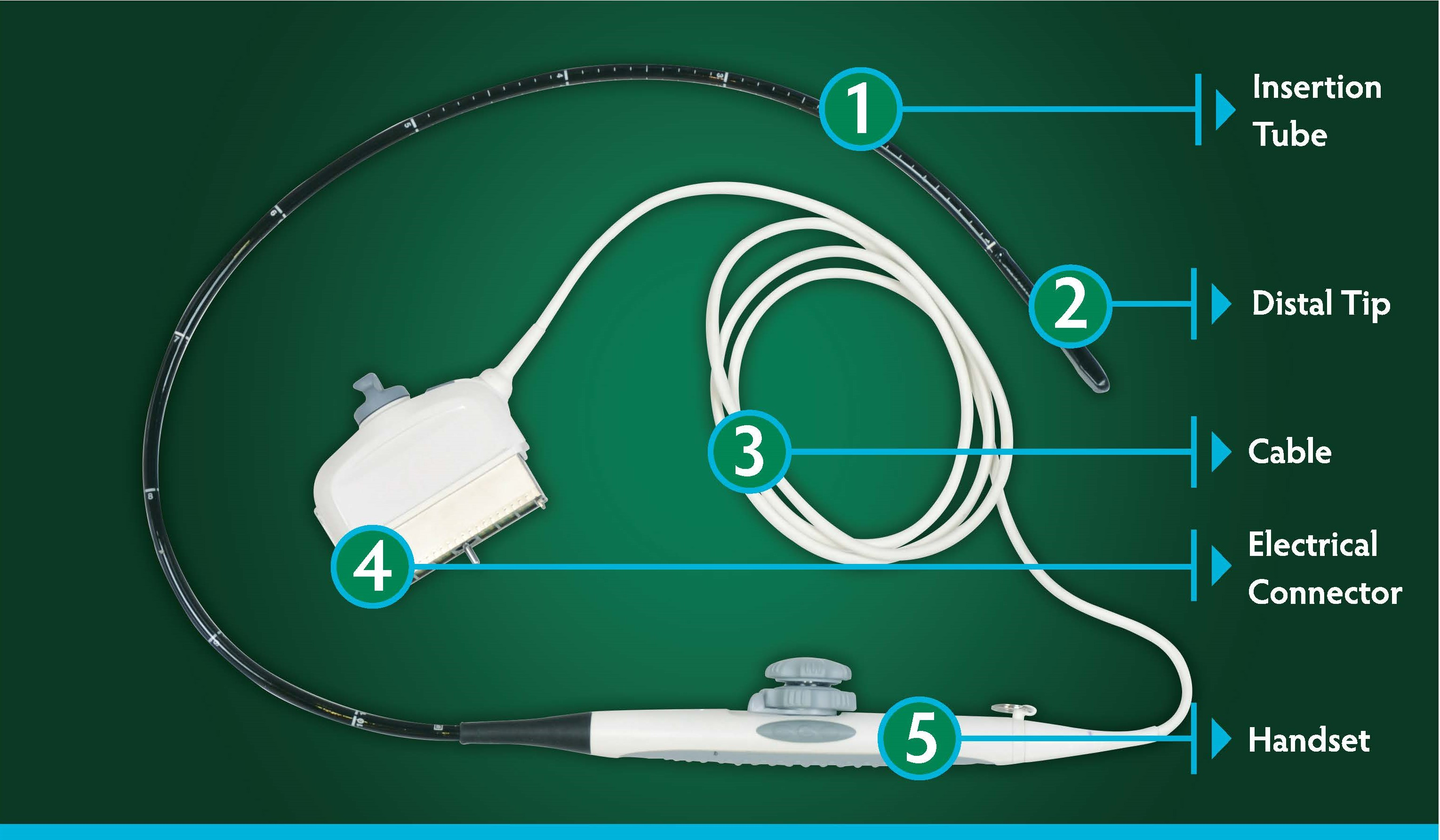
TEE Probe Articulation Wear: The Check With No Baseline
A TEE probe's bending section cannot report its own condition, and some current models publish no deflection range to compare it against. What each class of document can settle — and the baseline you have to record yourself.
Which Endoscope Specifications Change the Device, Not Just the Model
A specification sheet interleaves two kinds of fact and presents them in the same format: what the instrument is, and which version of it you have. This is how the parameters group, where the design trade-offs are documented, and where the category boundaries actually fall.